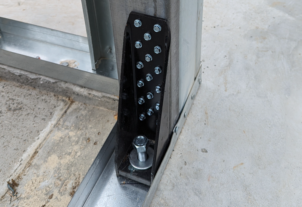
Understanding Holdowns in Light Steel Frame (LSF) Structures: Types, Capacities, and Applications

Holdowns are critical components in light steel frame (LSF) structures. They are designed to resist uplift and overturning forces caused by lateral loads, such as wind or seismic forces. Below is a detailed overview of holdowns and their application in LSF structures:
What Are Holdowns?
Holdowns are structural connectors that anchor the steel frame to the foundation or another supporting structure. They are typically installed at the ends of walls or other critical points in the frame to transfer forces from the structure to the foundation.
Purpose of Holdowns in LSF Structures
-
Resisting Uplift Forces:
- Wind or seismic events can create uplift forces that try to pull the wall or frame away from the foundation. Holdowns secure the frame in place.
-
Preventing Overturning:
- Lateral forces on walls can cause overturning moments. Holdowns counteract these moments by anchoring the frame to the foundation.
-
Load Transfer:
- They ensure the effective transfer of loads (axial, lateral, or uplift) to the foundation or supporting elements.
Key Components of a Holdown System
-
Anchor Bolts:
- Typically embedded in the concrete foundation.
- Connect the holdown to the foundation.
-
Straps or Brackets:
- Made of high-strength steel.
- Attach to the vertical studs or end posts of the LSF wall.
-
Fasteners:
- Screws or bolts that secure the holdown to the steel frame.
- Should comply with specific design requirements (e.g., shear and tensile strength).
Types of Holdowns Used in LSF Structures
-
Fixed Holdowns:
- Installed permanently at critical points like wall ends or openings.
- Designed for large uplift or overturning forces.
-
Adjustable Holdowns:
- Provide flexibility during installation.
- Common in structures where precise alignment is required.
-
Continuous Rod Holdown Systems:
- Use threaded rods extending through multiple floors to transfer forces directly to the foundation.
Design Considerations
-
Load Requirements:
- Determine the uplift and lateral loads based on wind and seismic forces.
-
Connection Details:
- The connection between the holdown, frame, and foundation must meet the required load capacities.
-
Spacing:
- Holdowns are typically installed at each end of shear walls or where significant loads are expected.
-
Material Compatibility:
- Use corrosion-resistant materials (e.g., galvanized steel) in environments prone to moisture or chemical exposure.
Common Standards and Guidelines
- ASCE 7 - Minimum design loads for buildings and other structures.
- ACI 318 - Design provisions for anchor bolts in concrete.
- AISI S100 - North American specification for the design of cold-formed steel structures.
The load-bearing capacity of holdowns depends on several factors, including the type of holdown, the size of the holdown, the type and number of fasteners, and the base material (e.g., concrete or wood). Below is an example table illustrating approximate load capacities for commonly used holdowns in light steel frame (LSF) structures. These values are generalized and should always be confirmed with manufacturer specifications.
Holdown Load-Bearing Capacity Table (Approximate)
| Holdown Size | Number of Fasteners (Screws/Bolts) | Uplift Capacity (kN) | Shear Capacity (kN) | Embedment Depth (mm) |
|---|---|---|---|---|
| Small (e.g., H1) | 4 screws (No. 10) | 5–10 | 3–6 | 75–100 |
| Medium (e.g., H2) | 6 screws (No. 10) | 10–20 | 8–12 | 100–150 |
| Large (e.g., H3) | 8 screws (No. 12) | 20–40 | 12–20 | 150–200 |
| Heavy Duty | 12 screws (No. 14) | 40–70 | 20–35 | 200+ |
Notes on the Table:
-
Load Capacity Variations:
- Capacities depend on the grade of fasteners and the type of connection material (e.g., concrete strength, steel thickness).
-
Manufacturer-Specific Data:
- This table provides general guidance. For precise values, refer to manufacturer technical documentation such as those from Simpson Strong-Tie, Hilti, or Pryda.
-
Installation Details:
- The embedment depth refers to the anchor bolt's depth in the concrete or substrate.
- Proper tightening and positioning significantly impact the holdown's performance.
-
Load Testing:
- Capacities are typically determined via laboratory testing under specific conditions (e.g., edge distance, anchor spacing).
Example Applications:
- Small Holdowns: Used for light-duty applications such as anchoring non-load-bearing walls.
- Medium Holdowns: Typical for standard shear walls in single-story LSF structures.
- Large Holdowns: Applied in high-load scenarios, such as resisting seismic or strong wind forces.
Installation Tips
- Ensure proper alignment of the holdown with the frame and anchor bolts.
- Follow manufacturer instructions for bolt tightening and connection details.
- Inspect holdowns periodically for signs of damage, corrosion, or loosening.

